Contents
Introduction
The goal of this project was to learn more about telemetry systems and the MQTT protocol. The system combines a PID speed controller with remote speed control and measurement of the motor’s voltage, current, and power. It also used two hardware platforms and development environments: STM32CubeIDE and the Espressif IDF.
The result is a complete SCADA-style system. When the motor comes under unusually high load and the current rises well above the expected level, the system issues a warning. The motor can run in an automatic mode, where its speed steps through a defined sequence, or be controlled manually. Sampling is deterministic and the sample interval is adjustable, and readings can be recorded to a CSV file for later visualisation and analysis.
General system architecture
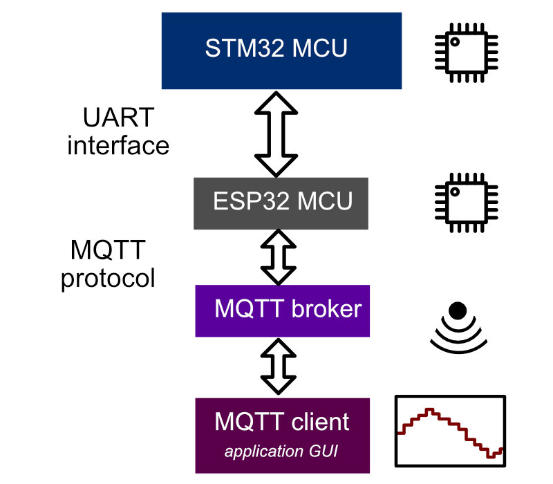
System architecture: two microcontroller boards (STM32 and ESP32) and a locally hosted MQTT broker.
STM32 Microcontroller
The STM32 is responsible for data acquisition and direct motor control. The system runs on FreeRTOS to ensure tasks execute simultaneously and their timing remains deterministic. Mutexes, queues, and other RTOS mechanisms are used for sharing resources between tasks.
Peripherals configured and wired up:
- INA228 sensor — voltage, current, and power measurements
- Incremental motor encoder — rotational speed
- TM1650-based four-digit 7-segment LED display
- ESP32 connection via UART
ESP32 Microcontroller and MQTT Broker
The ESP32 devboard acts as a bridge between the STM32 and the MQTT broker. It communicates with the STM32 via UART and, because it has a built-in wireless module, it can connect to the MQTT broker and publish data to the telemetry topic. The broker then delivers the data to any subscribed client — in this case, a desktop GUI application running on a PC.
Software architecture
FreeRTOS tasks on STM32
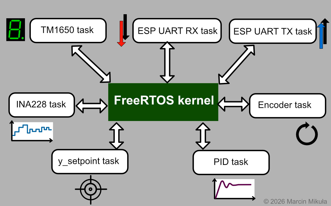
Overview of the FreeRTOS task structure on the STM32.
The software is split into several tasks executed by the FreeRTOS kernel, keeping their behaviour deterministic:
- INA228 task — initialises and reads from the INA228 sensor, then puts a structure (current, bus voltage, power) into a message queue consumed by another task
- TM1650 task — takes control of the LED display so the speed in RPM is visible to the user
- ESP UART TX task — parses data received from other tasks and sends it via UART to the ESP32
- ESP UART RX task — receives messages from the ESP32 and forwards commands (mode and setpoint) to the setpoint task
- Encoder task — initialises the hardware timer in encoder mode and calculates rotational speed in RPM
- Setpoint task — sets the target speed value, managing both automatic (sequential) and manual mode
- PID task — governs the PID controller operation
The graphical user interface
GUI design requirements
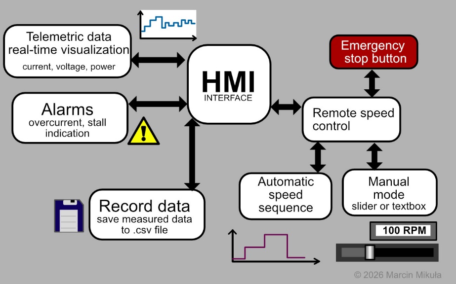
Diagram of GUI features and their interconnections.
The GUI includes the following features:
- Real-time plots of the measured and received data
- Alarm set indicating dangerous situations: overcurrent, motor stall, overheat (planned in next release)
- Motor speed control with automatic mode (preprogrammed sequences) and manual mode (textbox + slider + confirmation button)
- Emergency stop button — the motor stops immediately
- CSV data export for further analysis (PID step responses, power consumption, efficiency)
Implementation
Data acquisition — STM32 MCU
Digital PID controller and PWM output
The PID controller was implemented in its discrete form. Its key features are: configurable parameter settings, output saturation, and an anti-windup method (clamping). The theory behind the algorithm is covered in detail in a separate article: PID Controller — Theory and Practice.
Below are fragments of the PID implementation in embedded C:
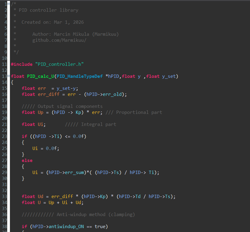
Calculating PID output signal components — a fragment of the PID calculation function.
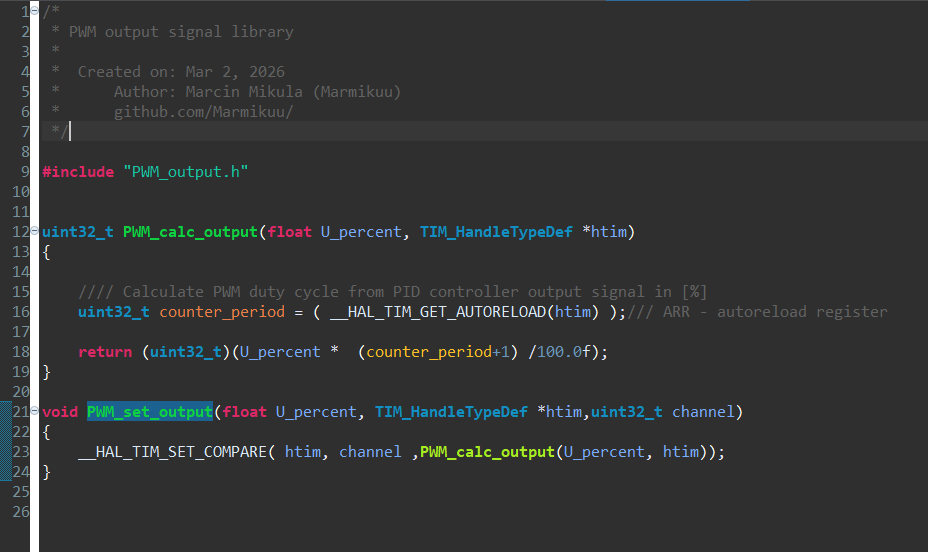
PWM output functions — setting the duty cycle from the controller output.
The PID controller output signal is converted to a PWM duty cycle in the range 0–100%. Because the motor requires a separate power supply, the STM32’s PWM output is connected to the Cytron MD13S motor driver PCB, which controls the motor directly. The PWM timer was configured in STM32CubeIDE to operate at 20 kHz, which reduces acoustic noise. The captures below were taken at a lower frequency so the waveform is clearly visible on a basic oscilloscope.
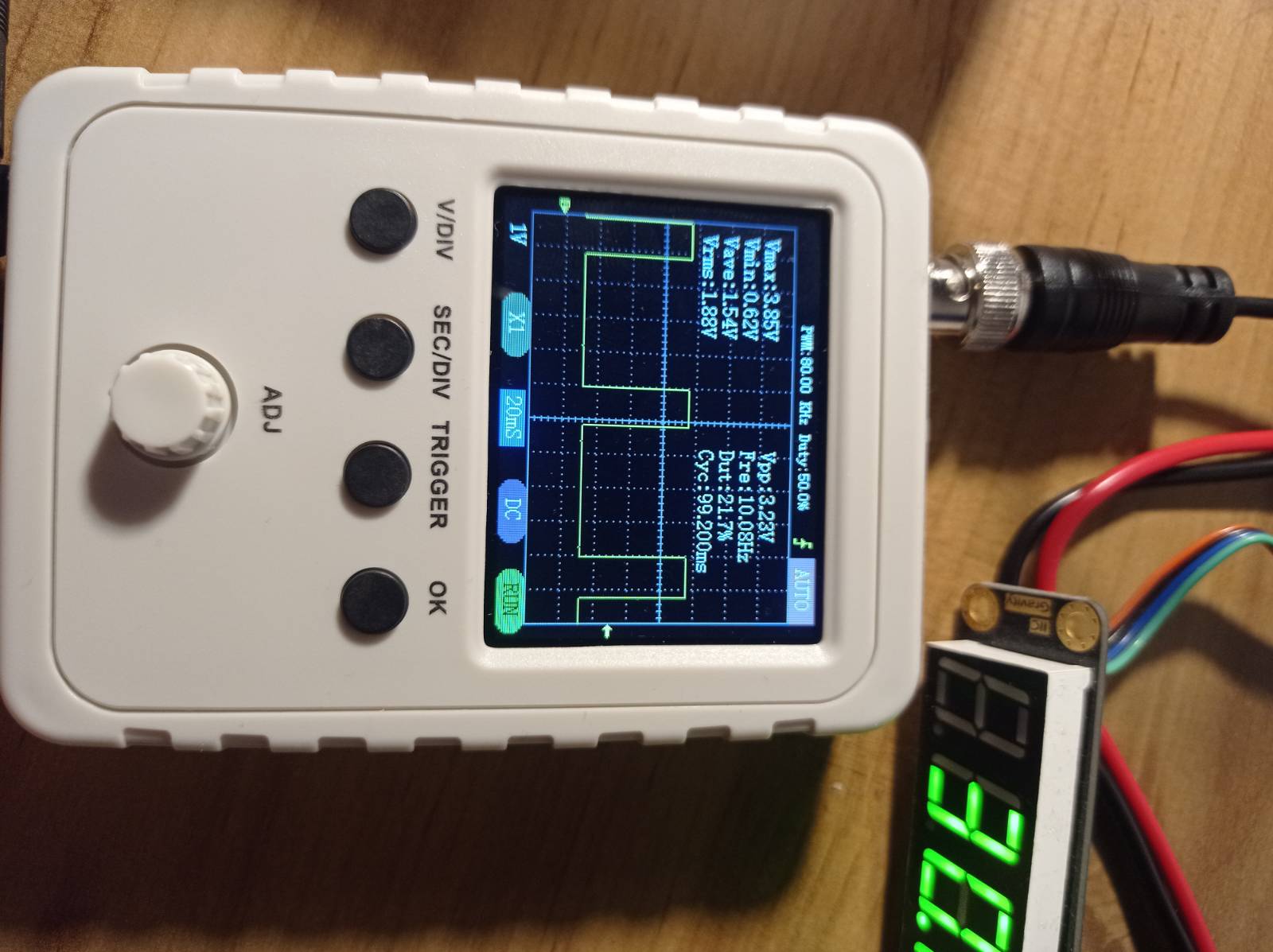
PWM signal measured on an oscilloscope.
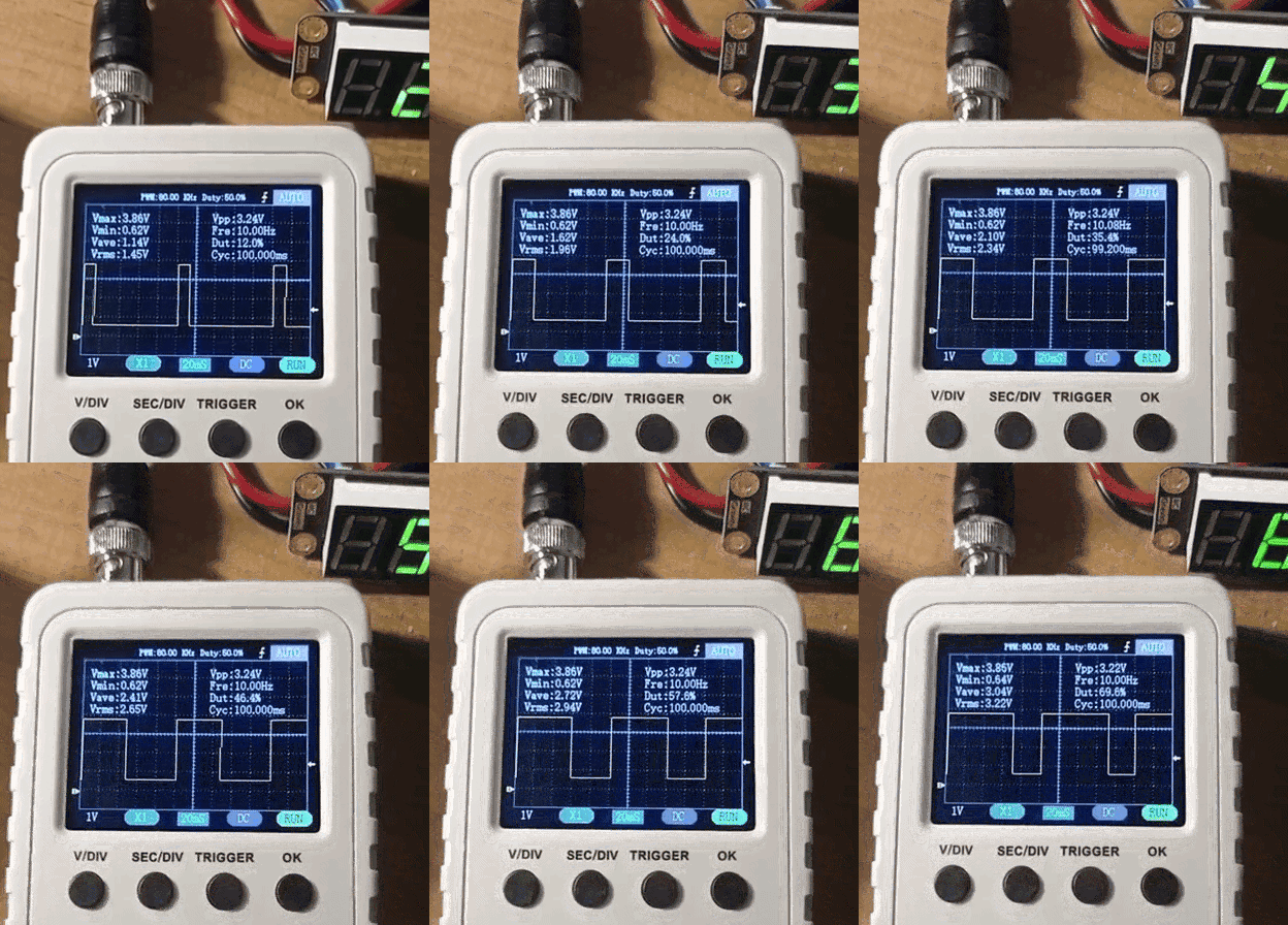
PWM duty cycle changing — captured on oscilloscope.
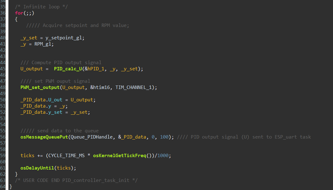
PID task structure and the use of PID and PWM libraries.
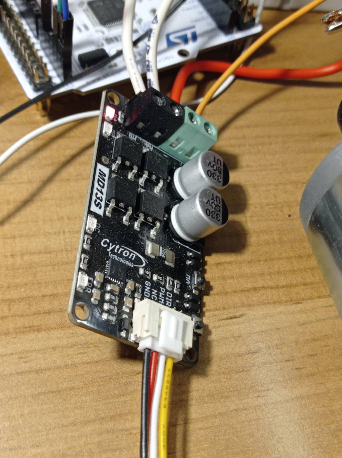
Cytron MD13S motor driver PCB, controlled by the STM32’s PWM output signal.
The PID controller and PWM output libraries are available in the GitHub repository: github.com/Marmikuu/STM32_Embedded_Control_Systems.
INA228 sensor
For electrical measurements (voltage, current, and power), an INA228 sensor was used. It is a high-end sensor with a 20-bit ADC and a current range up to 10 A. It is shunt-based: a small voltage drop across a shunt resistor is measured while current flows, and the current is calculated from it.
The INA228 was connected to measure the motor driver’s power supply rather than the motor terminals directly. Because the motor is driven by a PWM signal from the Cytron driver board, measuring at the motor output would mean measuring a fast-switching waveform, which the INA228 is not designed for — according to the datasheet it should be used for DC or slowly varying signals. Placing it on the driver’s DC supply avoids this.
No working STM32 driver for the INA228 existed, so the library was written from scratch using the datasheet. It is available here: github.com/Marmikuu/INA228_STM32_driver.
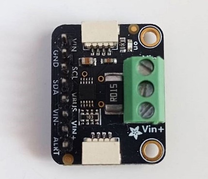
INA228 sensor (Adafruit’s PCB design).
The crucial INA228 parameters are the ADC averaging count and the conversion time. With a low averaging setting, the measurements are noticeably noisy; increasing it cleans them up at the cost of some dynamic response.
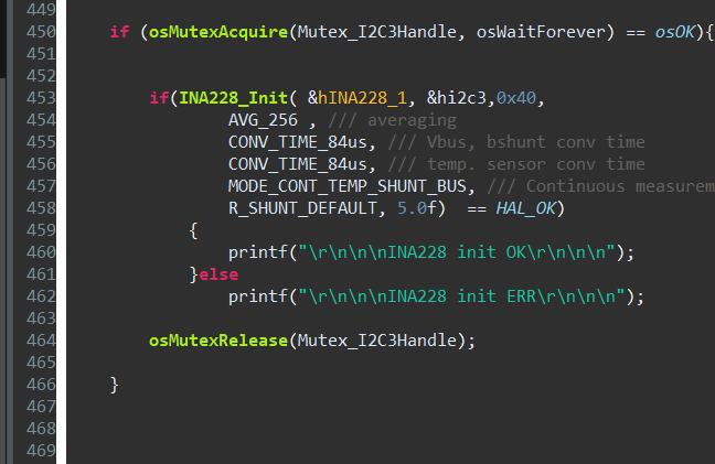
INA228 ADC configuration: averaging 256 samples and conversion time 84 μs.
The difference is clearly visible in this example from a related Li-ion battery project:
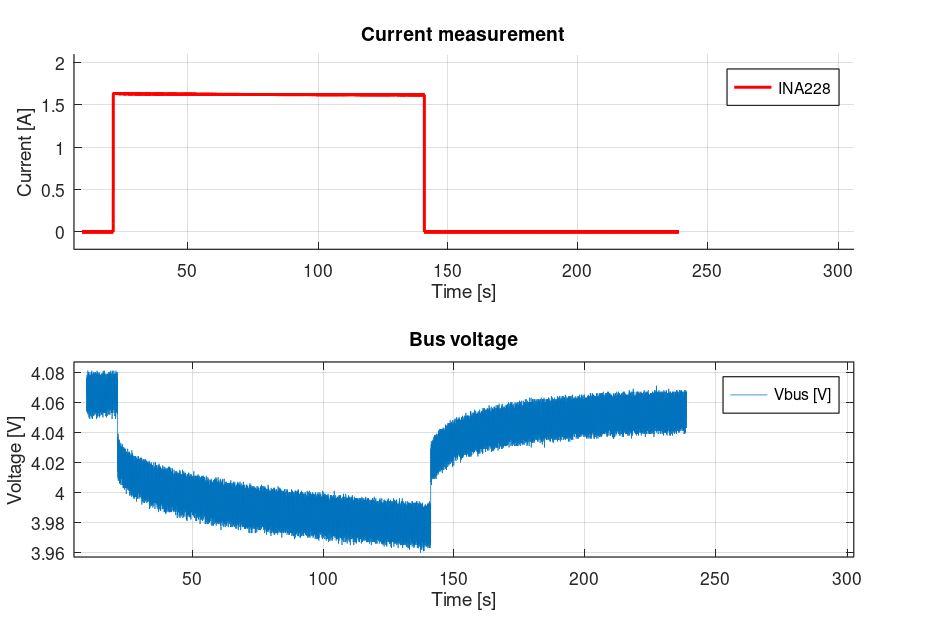
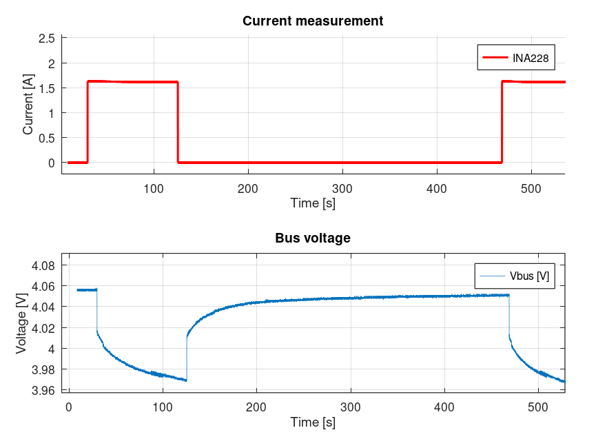
INA228 readings with AVG_16 (left, noisy) vs AVG_256 (right, clean).
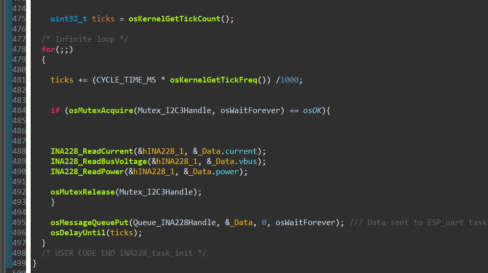
INA228 task: reading from the sensor and sending the measurement to the queue.
The INA228 task uses several FreeRTOS mechanisms. The I2C bus is protected by a mutex (shared with other tasks), and once a reading is taken the values are placed into a queue. The cycle time is kept constant using osDelayUntil, which guarantees a deterministic period rather than simply delaying by a fixed amount after each iteration.
TM1650 7-segment LED display
The project uses a 4-digit LED display based on the TM1650 driver. As no STM32 library was available, one was written from scratch using the manufacturer’s datasheet. The display shows rotational speed in RPM to one decimal place, updated every 100 ms — a good compromise between digits that update too slowly and flicker that is too fast.
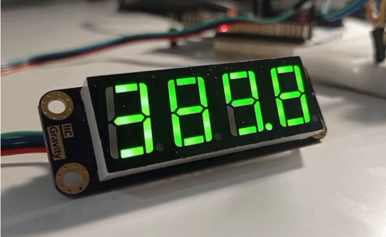
Motor speed in RPM shown on the 4-digit LED display.
The TM1650 communicates over an I2C interface, but it is not a standard I2C device — there is no single device address; instead, command addresses and their corresponding instructions are sent. During integration, a problem appeared: the TM1650 interfered with the INA228 because one of its undocumented commands used the same address as the current sensor. The solution was to place the two devices on separate I2C buses.
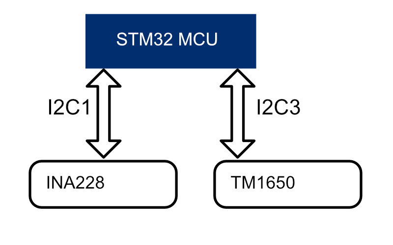
Separate I2C buses for the TM1650 display and the INA228 sensor, so each device operates independently.
The LED display driver for STM32 is available here: github.com/Marmikuu/TM1650_STM32_driver.
Incremental motor encoder
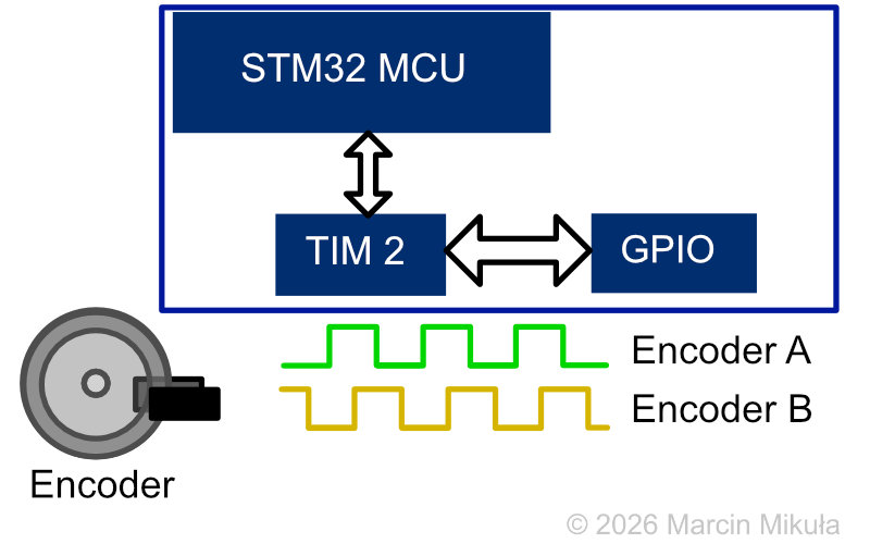
Two-channel motor encoder outputs connected to STM32 GPIO inputs — ticks counted by hardware timer TIM2.
The motor had a two-channel incremental encoder, connected to the STM32 through digital inputs with pulse counting handled entirely in hardware. This offloads the processor, which would otherwise have to service a very large number of interrupts. TIM2 was used in encoder mode, configured for two input channels — this makes it possible to measure rotational speed in both directions. A built-in hardware filter suppresses noise.
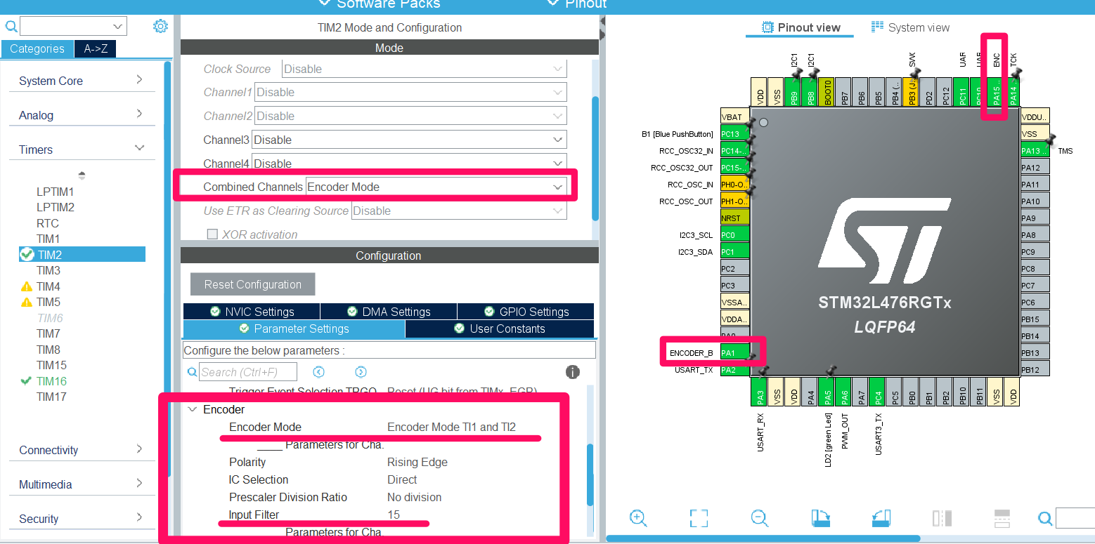
STM32CubeIDE timer configuration — TIM2 in encoder mode.
Wireless MQTT communication — ESP32
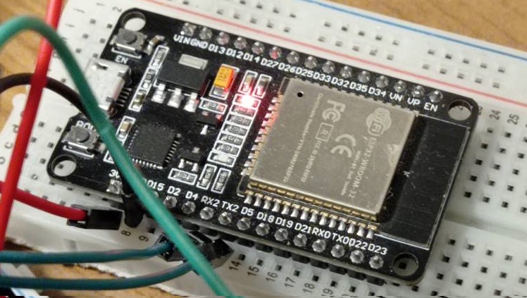
ESP-WROOM-32 development board — UART bridge between STM32 and the MQTT broker.
The ESP32 was wired to the STM32 for UART communication. Its built-in wireless module is used to connect to the MQTT broker and relay data between the microcontroller and the desktop application.
MQTT protocol
MQTT (Message Queuing Telemetry Transport) is a lightweight publish/subscribe network protocol designed for IoT devices. Instead of devices talking to each other directly, they publish messages to topics on a central broker, and any device subscribed to a topic receives those messages. MQTT also defines Quality of Service (QoS) levels: the higher the level, the stronger the delivery guarantee, at the cost of more network overhead.
In this project the broker is a Mosquitto server running locally on a PC, acting as the hub between the ESP32 and the desktop GUI. The following topics are used:
- Speed setpoint — sends the target speed in RPM from the GUI to the STM32 (via ESP32). QoS 0.
- Mode command — carries the operating mode (automatic or manual). QoS 0.
- Telemetry data — timestamp, voltage, current, power, measured RPM, setpoint RPM, and PID output. Published by the STM32, displayed by the GUI. QoS 0.
- Emergency stop — stops the motor immediately. QoS 1, so the message is acknowledged and guaranteed to arrive.
The QoS choices are deliberate. Telemetry and speed commands use QoS 0 (“at most once”) because they are sent frequently and a single dropped message is immediately replaced by the next one. The emergency stop uses QoS 1 (“at least once”) because it is sent rarely but must not be lost — a dropped stop command is a safety problem.
It is worth noting that the primary safety functions run directly on the STM32: it stops the motor automatically when the overcurrent threshold is exceeded or a stall is detected. The MQTT emergency stop is an additional layer that lets the operator stop the motor remotely at any time. Because it depends on the network and broker being available, it complements rather than replaces the local hardware-level protection.
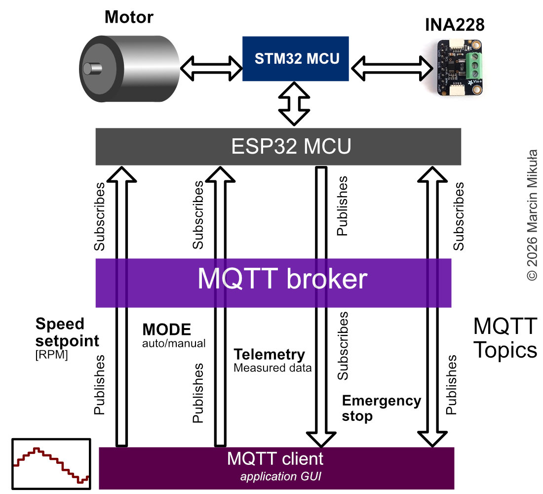
MQTT communication structure: the STM32 publishes telemetry (via ESP32), while the GUI publishes speed commands and the emergency stop — all messages pass through the local Mosquitto broker.
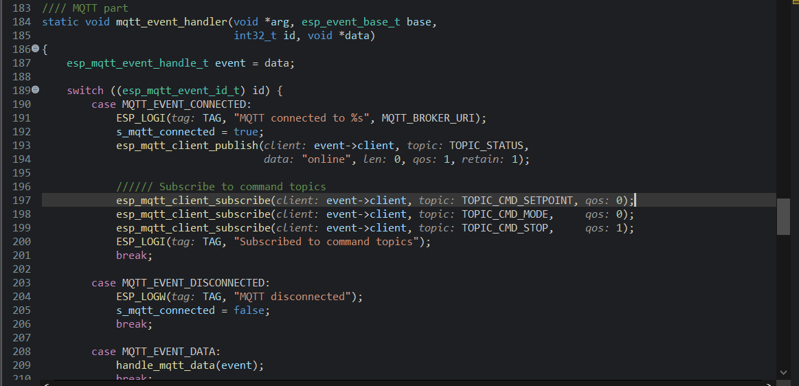
Part of the MQTT handling code in the Espressif IDF, flashed onto the ESP32. The event handler subscribes to the command topics and reports the device’s online status on connection.
The GUI
The GUI provides data logging, speed control, alarm indication, and threshold configuration that persists to a file between restarts. It was designed to be simple and clear, including only the necessary functionality. Power is not plotted separately, but its current value is shown at the bottom of the window.
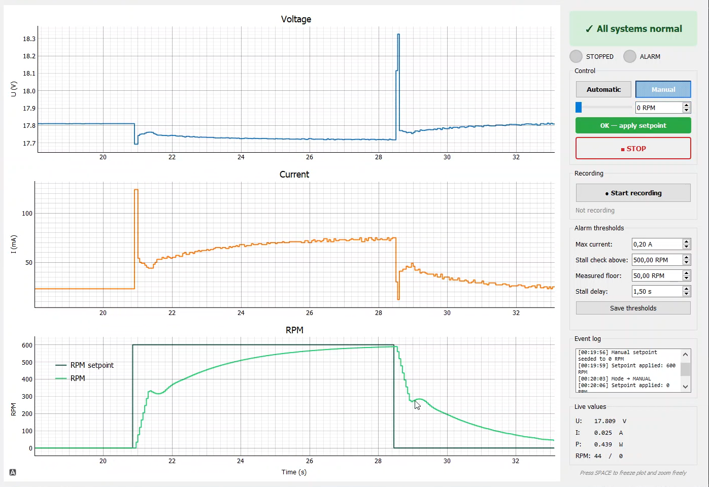
Overview of the desktop GUI — three real-time plots (speed, current, voltage) are visible.
Results and experiments
LED display operation and motor demonstration
The motor running at a setpoint of 600.0 RPM. The measured speed varies slightly over time, likely due to quantisation noise in the encoder readings or minor mechanical effects such as bearing friction.
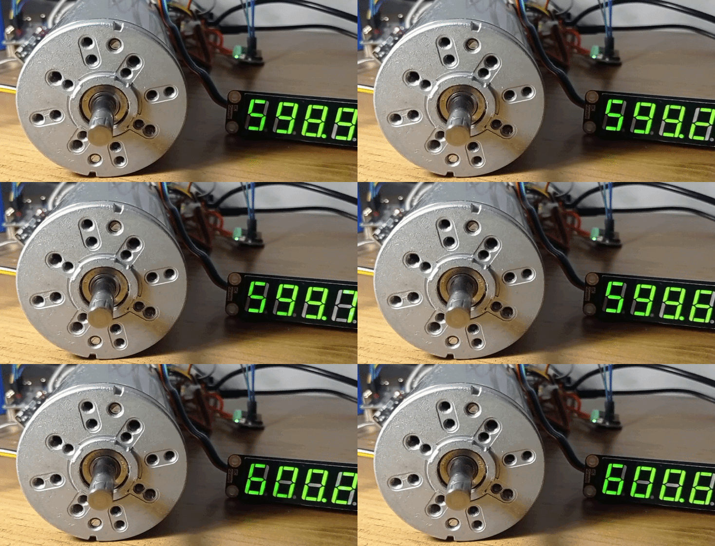
Motor running at 600 RPM — speed shown on the LED display.
Automatic and manual mode
Automatic mode
An example automatic mode sequence, where each setpoint holds for 20 seconds:
Speed sequence: 0 → 300 → 600 → 300 → 0 → 600 RPM
The data was recorded to a CSV file and plotted with an Octave script. PID parameters: Kp = 0.04, Ti = 10.0 s, Td = 0.0 s.
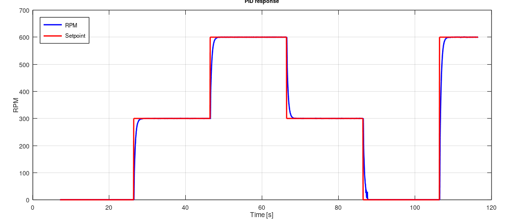
Automatic sequence plot — speed steps through the defined sequence, recorded and plotted with Octave.
Manual mode
The speed was changed manually in three steps. Each time the PID controller manages to reach the setpoint. It is worth noting that the current draw increases with each higher speed step.
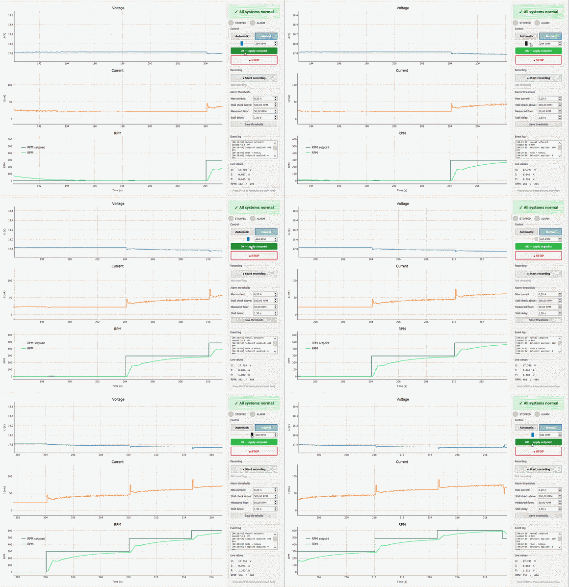
Manual mode — three speed changes applied through the GUI.
Motor under load
When the motor is placed under load, the current rises immediately. The PID controller adjusts its output signal in response: when a disturbance (the applied load) appears, the controller raises its output so the motor speed recovers to the setpoint.
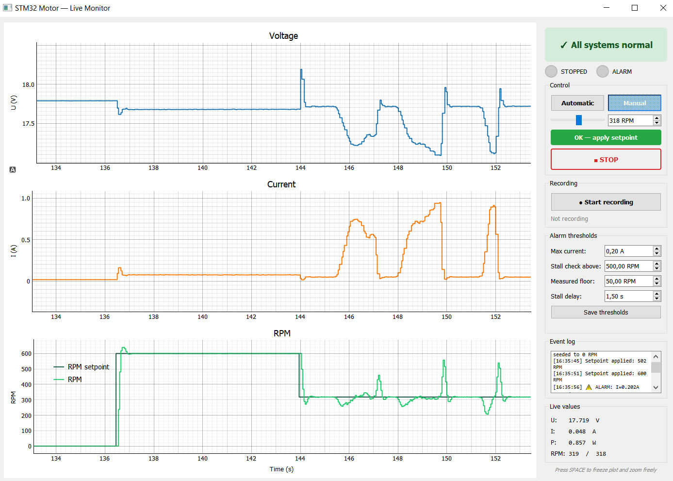
Motor under load: current rises immediately and the PID controller increases its output to maintain the setpoint speed.
Different PID parameters and step response
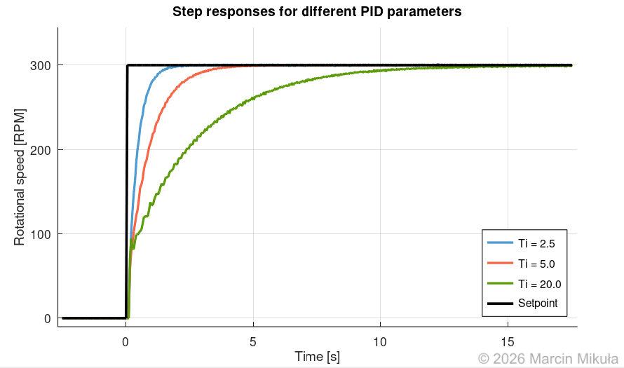
Step responses: integral time (Ti) experiment
An experiment where proportional gain Kp = 0.04 and derivative time Td = 0.0 s remain constant while integral time Ti is varied (0.5, 0.7, and 1.0 s). As the integral part works more intensively (smaller Ti), the oscillations grow. Conversely, a larger Ti slows the controller down and it requires more time to reach the setpoint.
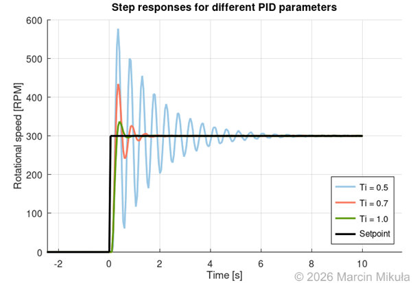
Step responses for Ti = 0.5 s (left) and Ti = 0.7 s (right) — smaller Ti causes more pronounced oscillations.
Conclusion
Several insights from finishing the project:
- Writing sensor libraries from scratch in embedded C was the hardest part. Datasheets are often around a hundred pages long, and turning that into a clean, modular driver takes considerable effort. In this case there was no choice, since no existing library was available — but in general, use existing libraries if they exist.
- Running the MQTT broker on a local server proved much faster than using a public broker, which is why a local Mosquitto instance was preferred.
- FreeRTOS is crucial in larger applications. It allows resources to be shared between tasks and provides synchronisation mechanisms: queues, semaphores, and task notifications. Although only a small piece of the API was used, it turned out to be remarkably beneficial.
- The INA228’s ADC parameters (averaging and conversion time) need to be tested early. With low averaging the measurements were noticeably noisy; increasing it cleaned them up at the reasonable cost of some dynamic response.
- The TM1650 display proved troublesome because it is not a standard I2C device. Its non-standard addressing collided with the INA228, which is why the two devices were eventually placed on separate I2C buses.
Future work
This project is an excellent foundation for further work, since its components are modular and reusable.
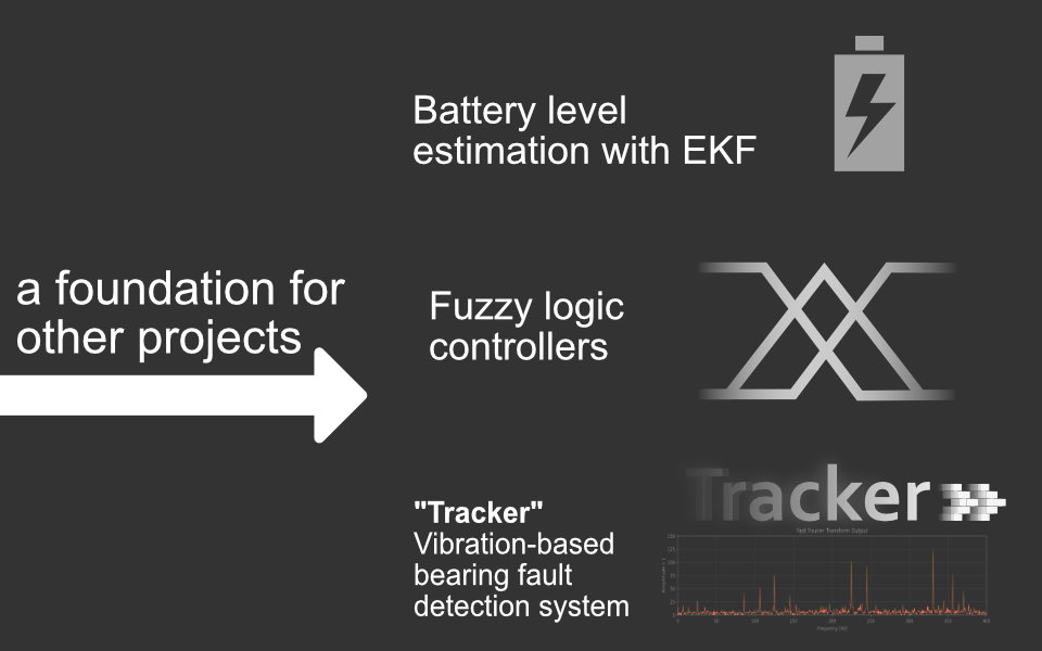
Future project architecture — the telemetry and control system as a foundation for further experiments.
The telemetry system architecture is general-purpose and can be reused for any project that relies on many short experiments and the need to collect measurements.
- The INA228 current sensor will be used in a project on Li-ion battery state-of-charge estimation with an Extended Kalman Filter.
- The motor and its speed control will serve a project on detecting ball-bearing faults from vibration measurements, using ADXL345 and IIS3DWB accelerometers.
- The code developed here — the PID controller, the PWM helper functions, and the drivers for the display and current sensor — is fully reusable.