Contents
Process of design
The project was made for educational purposes and some of its parts were made by the author with a student license (EPLAN schematics, SolidWorks 3D CAD model).
Requirements
1.1 Base & Extended Requirements
The course only required a basic project — a minimum of 3 actuators, a simulated analog sensor, an independent control system, and a basic, one-window HMI with step and auto mode and an Emergency Stop button. Use of three PLC programming languages: LD, ST, and SFC was required. That was the baseline.
Since I was simulating a real industrial process, I wanted to provide quality. The control system had to be robust, handle faulty scenarios, and give the operator full visibility and control over the process. The extended requirements I set for myself included:
- Real-time temperature plot — with simulated sensor noise to better reflect how a real measurement device behaves
- Step / Auto mode — in step mode every stage of the line executes sequentially and waits for operator confirmation before proceeding, giving full control during commissioning or testing
- START / STOP — the line can be stopped at any point and resumed without losing its state
- Acknowledge button — used both to confirm product collection and to clear fault states after the operator resolves the issue
- Service mode — allows the 2-axis manipulator to run in manual (JOG) mode with the ability to close the gripper manually, and to run the conveyor motor manually
- Timeouts — each process has its own time window to complete. If a product gets stuck or falls from the conveyor and isn't detected by the next sensor, the machine stops. This can also indicate a damaged sensor
1.2 Fault Simulation Scenarios
Real industrial lines fail — and a good control system must handle that gracefully. I designed several fault scenarios that can be triggered directly from the HMI to test the system's response:
- Compressed air supply fault — simulates a loss of pneumatic pressure. The gripper was deliberately chosen to be normally closed, so in the event of air loss the product is held rather than dropped
- Maximum oven power — forces the oven to run at full power, simulating a PCB overheat scenario. An overheated board is detected as defective by the quality inspection station and then routed to the NOK box
- Simulate defect — directly triggers a defect flag at the inspection station to verify the Pick&Place sorting logic works correctly
- Product drop — simulates a PCB pallet falling off the roller conveyor to test the timeout and fault recovery sequence
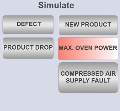
Fault simulation panel on the HMI — buttons for triggering each fault scenario during testing.
System overview
Overview of the SMT soldering line simulation — all stations and material flow from entry to sorting.
The SMT soldering line simulation assumes that solder paste has already been applied and components placed on the PCB — the simulation begins from the reflow stage onwards. The process follows four sequential steps:
- Product entry — the PCB pallet is placed at the start of the roller conveyor and begins moving down the line
- Reflow soldering — the PCB pallet moves to the reflow soldering oven, where it is heated according to the heat ramp and the reflow soldering process takes place
- Quality inspection — the pallet moves to the quality inspection station and is held by pneumatic stopper 1 while the product is tested
- Sorting — the pallet moves to the end of the conveyor and is stopped by pneumatic stopper 2. The 2-axis manipulator places the product in the correct box depending on the inspection result (OK — no defect, NOK — defective)
Sensors
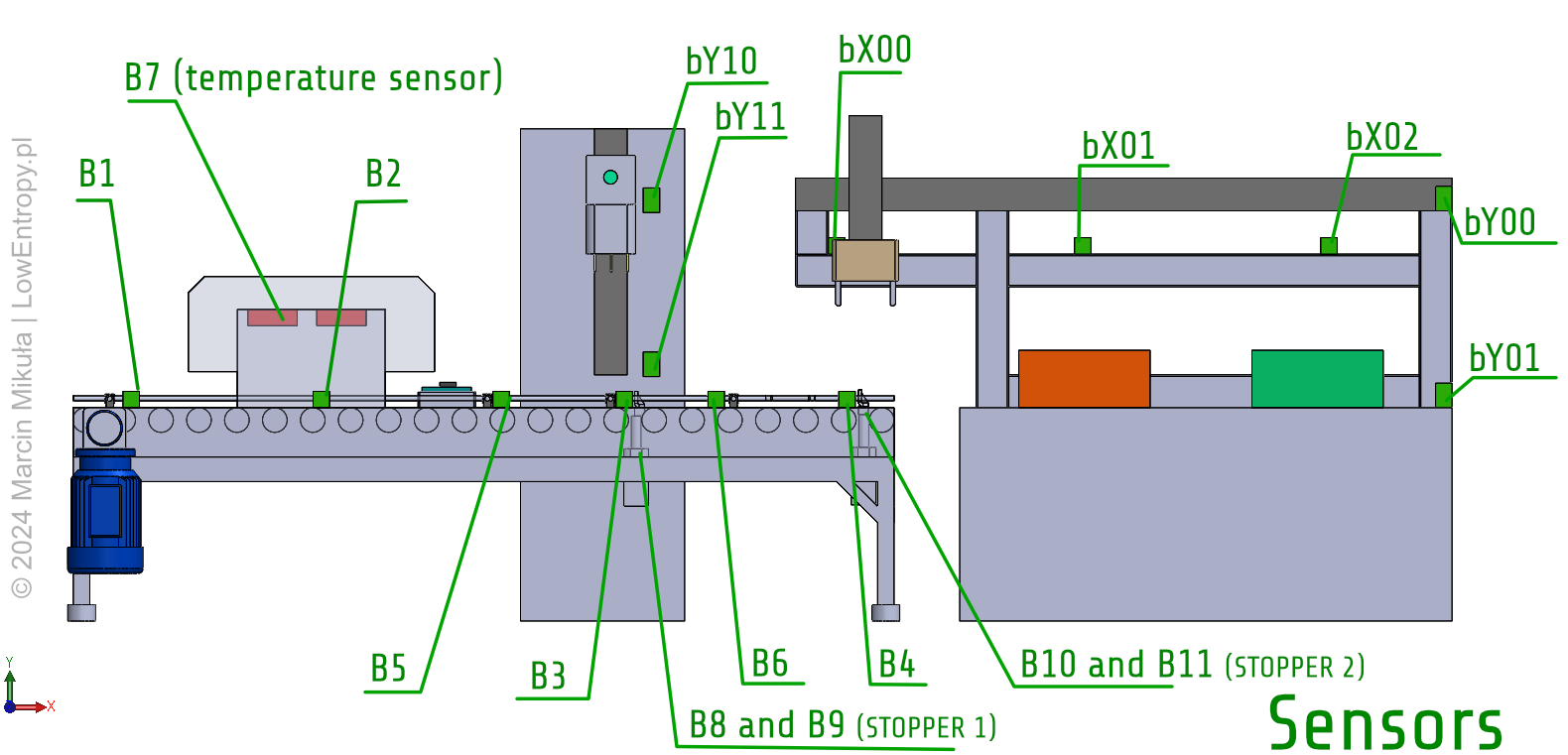
Sensor placement along the SMT assembly line.
| ID | Type | Description |
|---|---|---|
| B1–B4 | Inductive | Pallet detection along the roller conveyor |
| B5 | Inductive | Advance trigger — extends stopper 1 ahead of pallet arrival |
| B6 | Inductive | Advance trigger — extends stopper 2 ahead of pallet arrival |
| B7 | Temperature | Non-contact temperature sensor at the reflow oven |
| B8, B9 | Inductive | Stopper 1 cylinder position — B8 home, B9 work |
| B10, B11 | Inductive | Stopper 2 cylinder position — B10 home, B11 work |
| bX00–bX02 | Inductive | Manipulator horizontal (X axis) position |
| bY00–bY02 | Inductive | Manipulator vertical (Y axis) position |
| bY10–bY11 | Inductive | Inspection probe vertical (Y axis) position |
Actuators
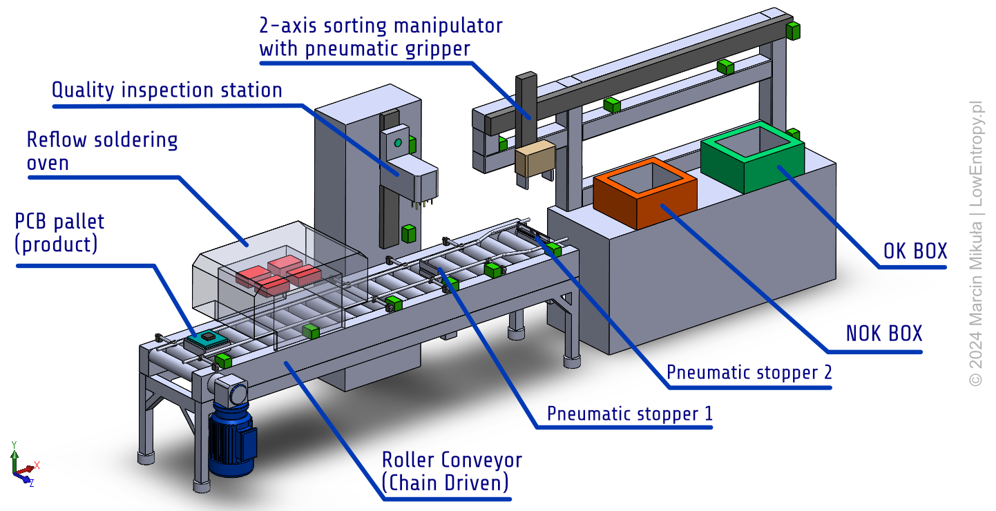
Actuators and their positions within the SMT assembly line.
| Actuator | Description |
|---|---|
| Conveyor motor | Electric motor driving the chain-driven roller conveyor |
| Reflow oven heater | Heating element inside the reflow soldering oven, controlled via analog output |
| Inspection probe — Y axis | Drives the quality inspection head vertically down onto the PCB pallet |
| Manipulator — X axis | Positions the sorting manipulator horizontally along the X axis rail |
| Manipulator — Y axis | Moves the 2-axis sorting manipulator vertically for pick and place |
| Pneumatic stopper 1 | 3/2 monostable solenoid valve — extends/retracts stopper 1 at the inspection station |
| Pneumatic stopper 2 | 3/2 monostable solenoid valve — extends/retracts stopper 2 at the sorting station |
| Pneumatic gripper | Normally closed gripper on the manipulator — holds the PCB pallet during sorting |
Mechanical design
The 3D model was created in SolidWorks 2020 Education mainly for visualization purposes. It served as a useful reference when preparing the BOM and designing the electrical schematic, making it much easier to identify sensor and actuator mounting positions. All models were made from scratch. One design decision worth noting — the pneumatic gripper was chosen to be normally closed, meaning it holds the product even when air pressure is lost. This directly ties into the compressed air fault scenario described in the requirements.
Electrical design
Bill of Materials
The Bill of Materials was prepared in Polish as the project was originally developed for a Polish university course. It lists all real, purchasable electrical components with part numbers, manufacturers, quantities, and suppliers — everything you would actually need to build this machine.
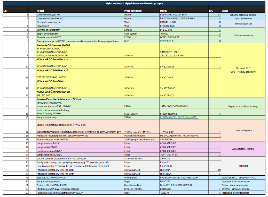
Bill of Materials — real industrial components with part numbers, manufacturers, and suppliers.
Electric Schematic in EPLAN Electric P8
The electrical schematic was prepared in EPLAN Electric P8 using a student license. It documents the wiring and connections of all components in the control system, including:
- PLC inputs and outputs
- Power supply and distribution
- Sensors
- Conveyor motor with soft start device
- Pneumatic solenoid valves
- Servo axis drives
Some components required simplification — the quality inspection device in particular, as such systems are highly application-specific and typically custom-built. It was included in the schematic but represented in a simplified form.
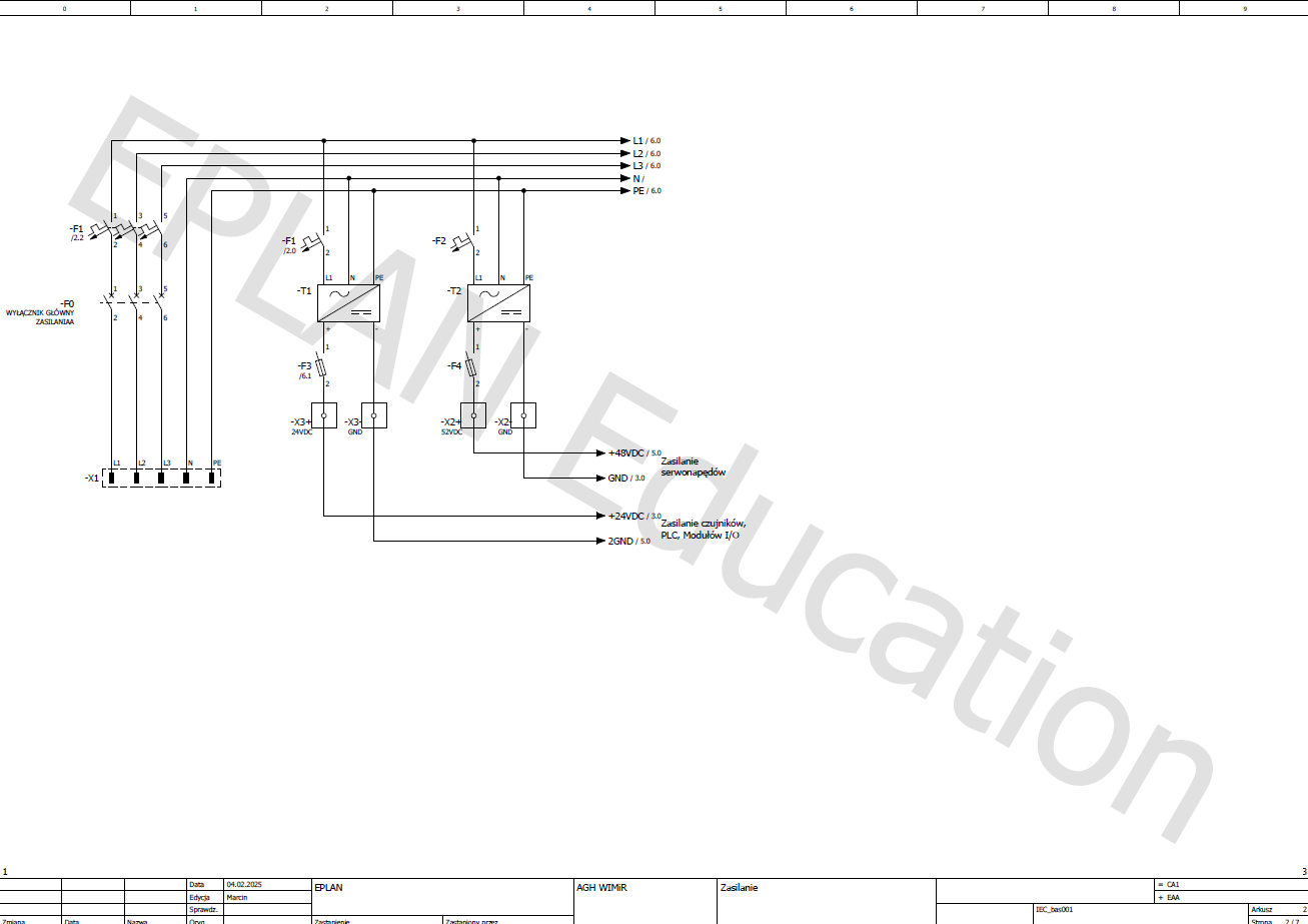
Power supply and distribution page from the EPLAN Electric P8 schematic.
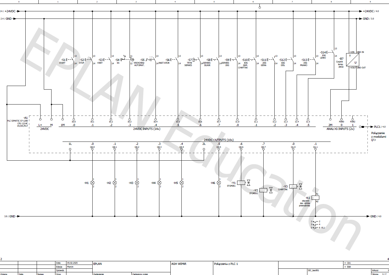
Operator panel connections — push buttons wired to PLC inputs.
PLC program architecture
The program was written in the CODESYS programming environment using three IEC 61131-3 languages, each chosen for a specific purpose:
- Ladder Diagram (LD) — used for low-level logic, such as simple signal conditioning and interlock conditions
- Structured Text (ST) — used for more complex functions, including the thermal object simulation and mathematical calculations
- Sequential Function Chart (SFC) — used to represent the main process sequence, defining transitions between stages of the line
Module organization
The code was organized into several functional modules:
- Simulation Function Blocks — one for each simulated device: conveyor, pneumatic stoppers, reflow oven, and the thermal transfer model
- Feature Function Blocks — PID controller, heat ramp management, and signal lamp operation
- Manipulator firmware — controls movement of the 2-axis manipulator to predefined positions with collision prevention, and implements JOG mode for manual operation
- Operator panel Function Blocks — handle button inputs and control panel logic
- Helper functions — including analog signal scaling and converting measured voltage to a physical temperature value
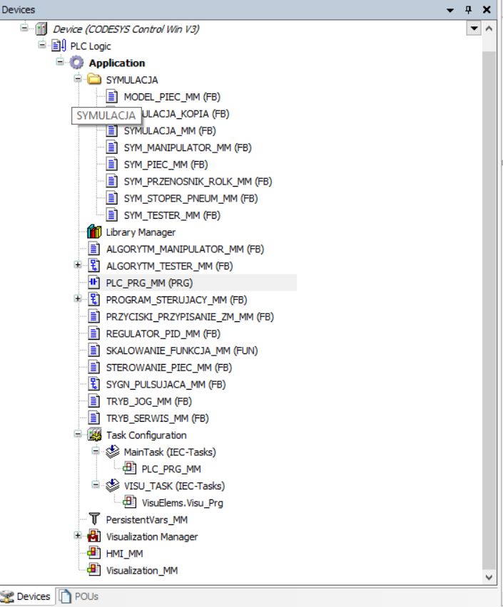
Structure of the PLC program in CODESYS — organized into simulation, feature, manipulator, operator panel, and helper modules.
Examples
Ladder Diagram
LD is used to call Function Blocks and connect them together. It provides a clear, visual representation of the control logic that is easy to read for anyone familiar with relay ladder logic.
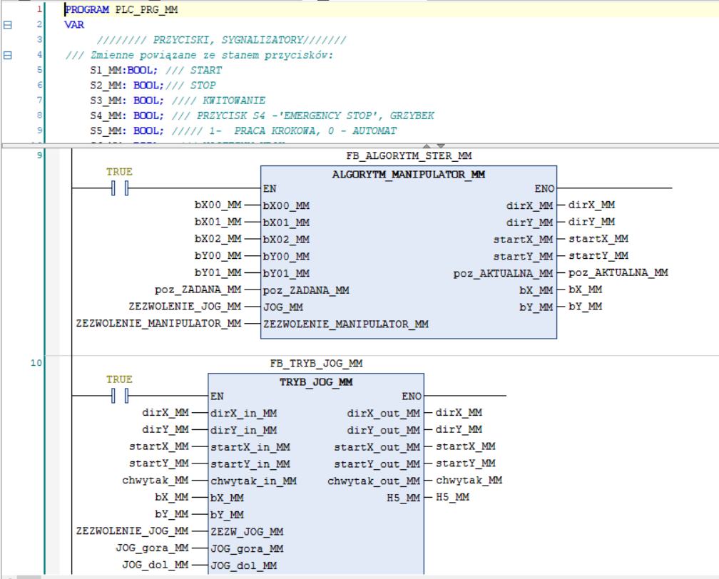
LD — used to call Function Blocks and connect them together.
PID Controller
The PID controller is implemented in Structured Text with an anti-windup feature. It controls the analog output driving the reflow oven heater, continuously adjusting the power output to follow the target temperature set by the heat ramp profile.
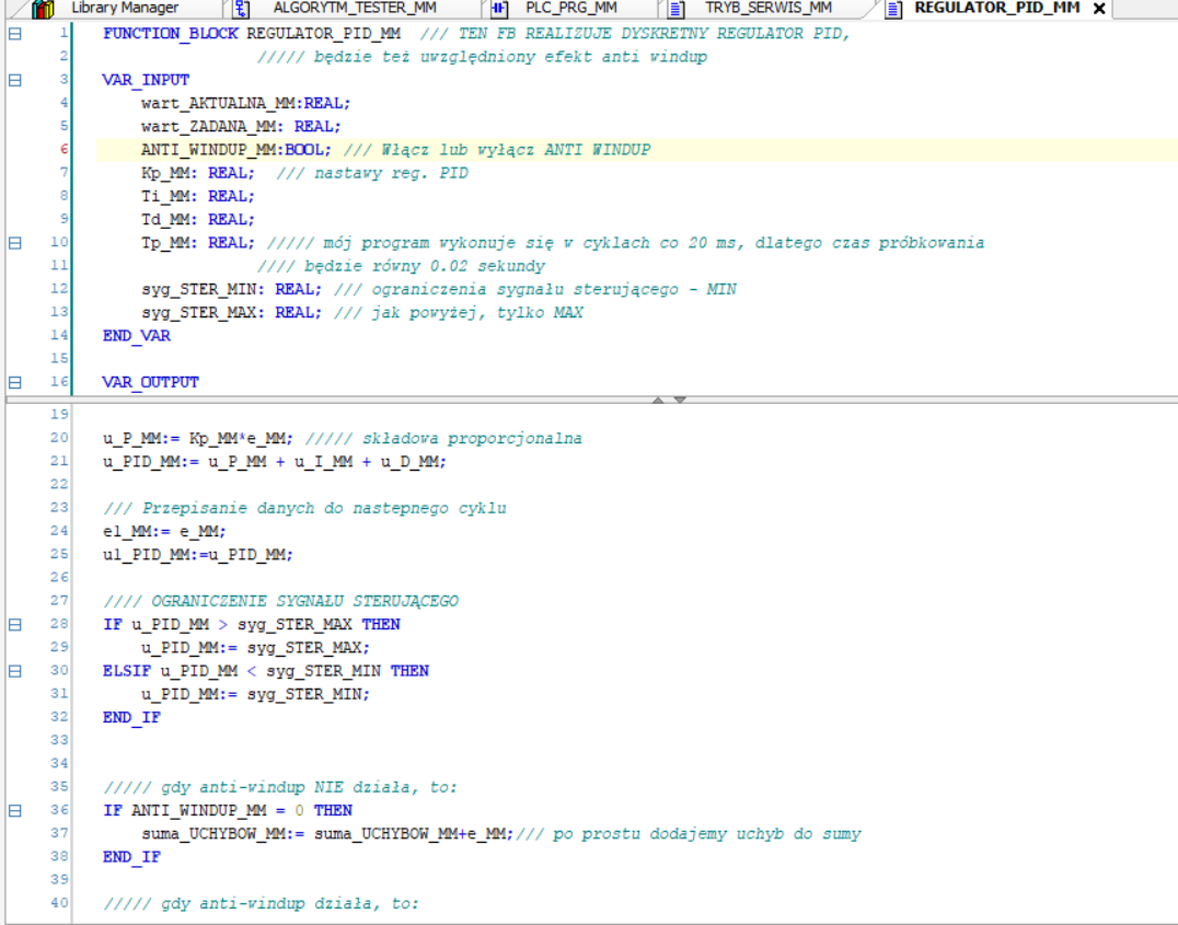
ST — PID controller implementation with anti-windup feature.
Heat transfer model of an oven
To make the simulation realistic, the reflow oven needed a proper thermal model. A first-order transfer function was chosen to mimic the dynamic behaviour of a real heating process — slow to respond, with a gradual temperature rise.
The continuous transfer function model was discretized to the Z domain and implemented as a difference equation in Structured Text, so the PLC can compute the simulated temperature at each scan cycle. This was necessary to close the loop with the PID controller — without a dynamic model, there would be nothing for the PID to control. The model parameters were tuned to allow the soldering process to complete in approximately one minute for demonstration purposes.
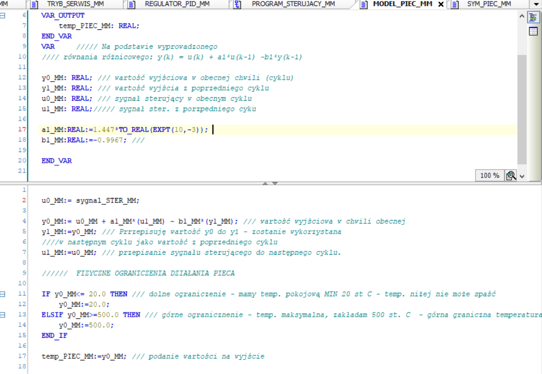
ST — mathematical model of the heat transfer in the soldering oven, implemented as a first-order difference equation.
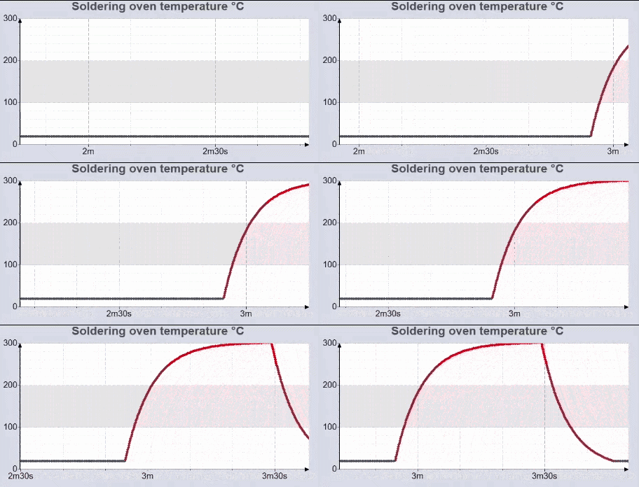
Animated presentation of the thermal model — simulated temperature response of the reflow oven under PID control.
Sequential Function Chart
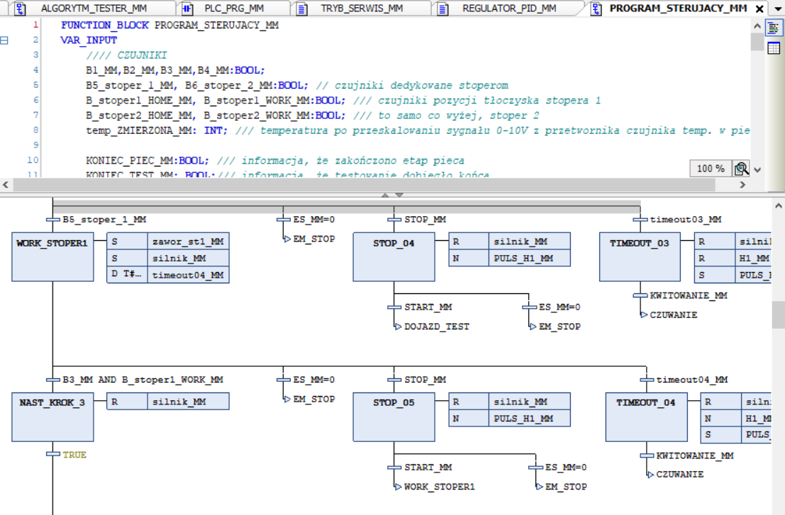
SFC — handling sequences, timeouts, and transitions between line stages.
HMI design
HMI control panel
The operator panel consists of four main buttons: START, STOP, ACKNOWLEDGE, and Emergency Stop (ES). A set of signal lamps indicates the current state of the machine, while two dedicated lamps display the quality inspection result — OK or NOK. A real-time temperature plot shows the heating curve as the oven works.
At the bottom of the panel, two additional sections are available. The Simulate section contains buttons for triggering fault scenarios and test conditions. The Service Mode section allows an operator to manually control the conveyor and the sorting manipulator — accessible only when the service key switch is activated.
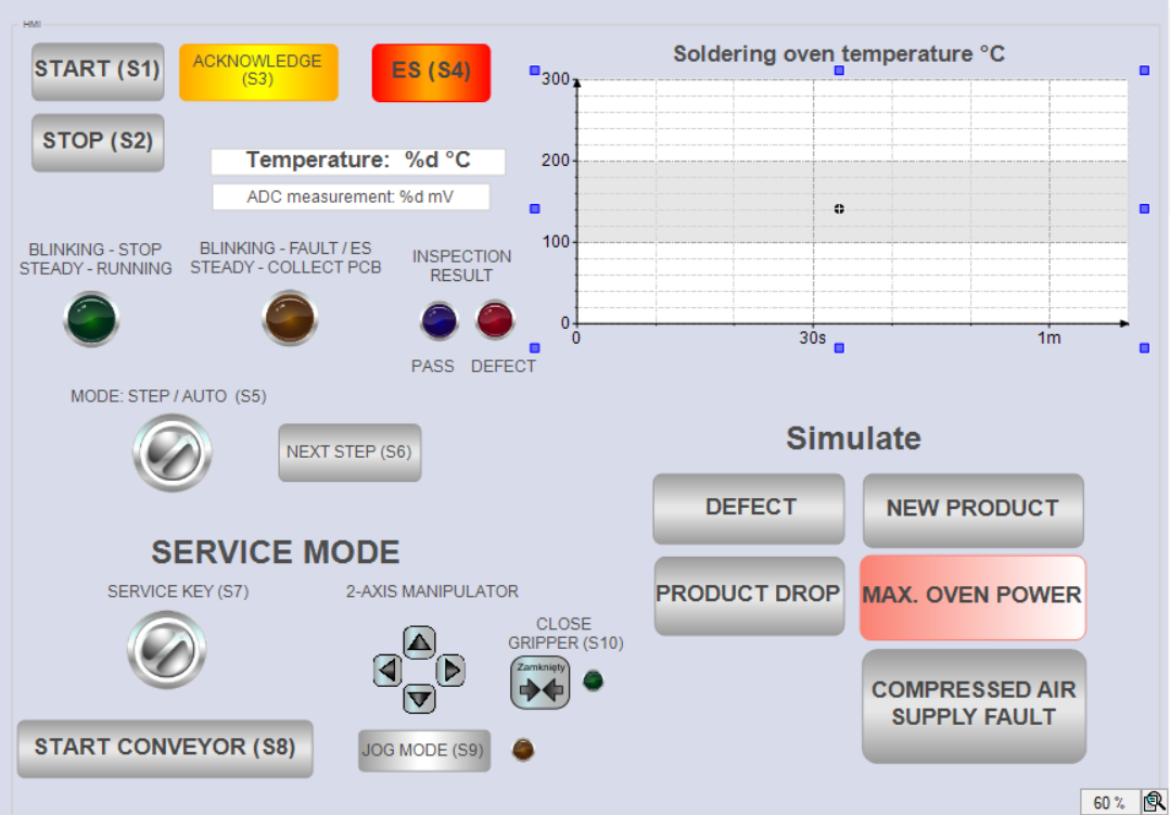
HMI control panel — START/STOP/ACK buttons, signal lamps, real-time temperature plot, simulate and service mode sections.
Simplified 2D simulation visualization
The HMI also includes a 2D visualization panel showing the machine in operation. The PCB pallet, reflow soldering oven, quality inspection device, and the 2-axis manipulator with pneumatic gripper are all visible and update in real time as the program runs.
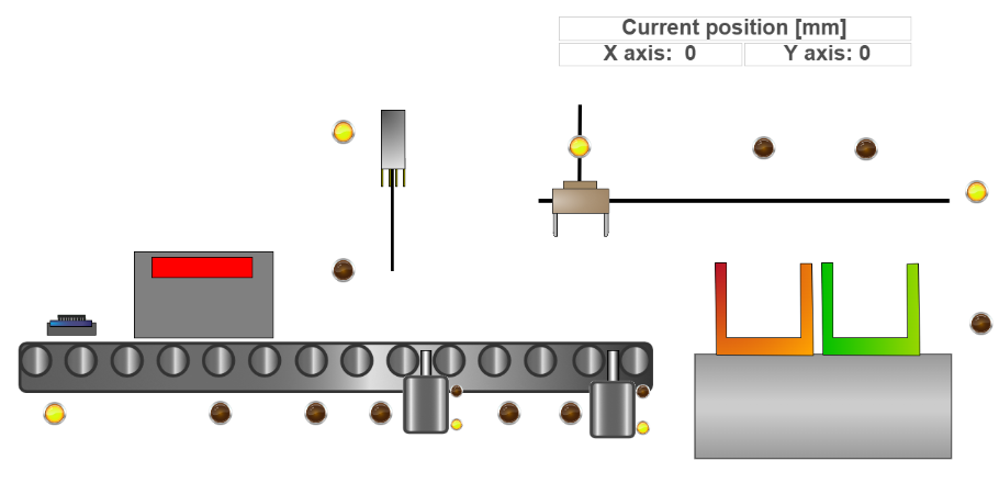
Simplified 2D visualization panel — real-time machine state display with pallet, oven, inspection, and manipulator.
System in action
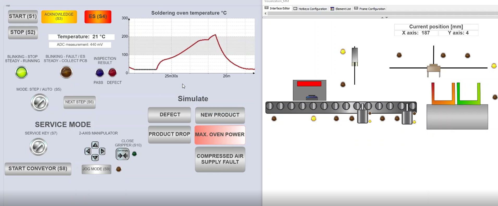
The SMT line simulation running in CODESYS — full cycle from product entry to sorting.
Technical documentation
The complete operation of the control system is described by a state machine diagram. It defines every state the machine can be in, the conditions required to transition between states, and how the system responds to faults, timeouts, and operator inputs. This was the foundation of the PLC program — the SFC (Sequential Function Chart) implementation in CODESYS follows this diagram directly.
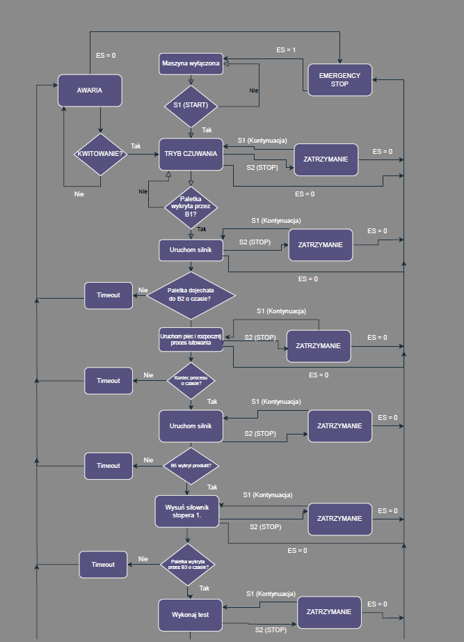
Fragment of the state machine diagram — conveyor start sequence and timeout handling.
References
- Altium Education — Fascinating Course about PCBs
- IPC-A-610J: Acceptability of Electronic Assemblies. IPC — Association Connecting Electronics Industries, 2024. Available at shop.electronics.org
- Panasonic — Temperature Profile for Connector Reflow Mounting
- AllPCB — SMT Reflow Soldering Profile
- ProtoExpress — Common Errors in SMT Soldering
- CODESYS — IEC 61131-3 Programming Environment